Translate this page into:
Assembling a make-shift light source for a radio frequency device for skin ablation
2 Department of Respiratory Medicine, William Harvey Hospital, Ashford, United Kingdom
3 Faculty of Dermatology, College of Medicine, King Faisal University, Hofuf, Saudi Arabia
Correspondence Address:
Karalikkattil T Ashique
Department of Dermatology, KIMS AL SHIFA Super Speciality Hospital, Perinthalmanna - 679 322, Kerala
India
| How to cite this article: Ashique KT, Kolakkadan K, Kaliyadan F. Assembling a make-shift light source for a radio frequency device for skin ablation. Indian J Dermatol Venereol Leprol 2017;83:268-269 |
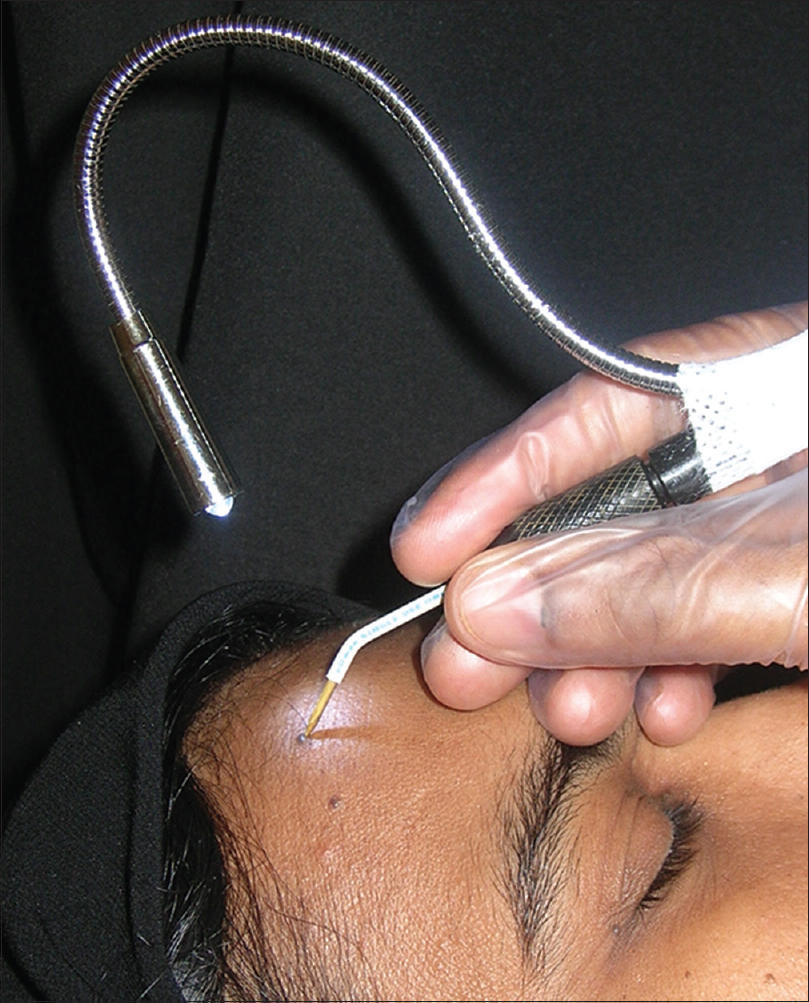
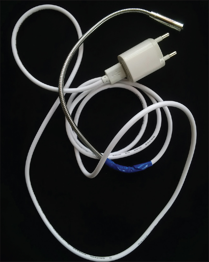
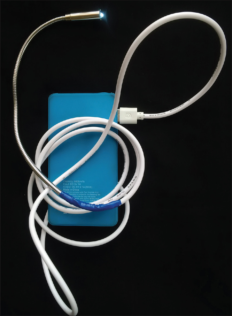
Radio frequency-based procedures are frequently performed in dermatology offices.[1],[2] The presence of brighter light in the operating field adds to the precision of the procedure and improves results. Lesions such as small skin tags or dermatosis papulosa nigra are better treated when there is optimal lighting. Adjusting light sources can be difficult in small-practice settings, where there is a single dermatologist. We have devised a “piggy back apparatus” with a light-emitting diode light source for making radio frequency machines (for skin ablation) useable even in a very dark room. A commercially available Chinese light-emitting diode light with a goose neck to make it flexible (predominantly marketed for lighting laptop keyboard with USB power), is used for this purpose. The apparatus basically works on 5 volts, deriving electricity from a USB source. The light-emitting end where the light-emitting diode is located is fixed with a tape as piggy back, which adds only 20 g to the weight of the hand piece [Figure - 1]. The USB end of the goose neck is extended by cutting the USB male jack which adds 1.25 m of wire in between. This makes the distance to the power source more versatile. The USB end is connected to any mobile phone charger or a portable energy bank (which works in the 5 Volt range) [Figure 2a] and [Figure 2b]. The advantage of the devise over commercially available light-emitting diode headgear is that in situ ations when the opposite side of the neck, axilla, abdomen of the patient is to be illuminated for procedure, the latter may not be able to throw adequate light as much as the illumination directly on the hand piece. The limitation of the modification is that the life of the light-emitting diode source is unpredictable which may warrant frequent replacement.
 |
| Figure 1: The mechanism at work with ample light thrown at the operating field |
 |
| Figure 2a: The light source with a mobile phone charger as the power source |
 |
| Figure 2b: The energy bank used as a portable alternative to power the device |
Financial support and sponsorship
Nil.
Conflicts of interest
There are no conflicts of interest.
| 1. |
Taheri A, Mansoori P, Sandoval LF, Feldman SR, Pearce D, Williford PM. Electrosurgery: Part I. Basics and principles. J Am Acad Dermatol 2014;70:591.e1-14.
[Google Scholar]
|
| 2. |
Taheri A, Mansoori P, Sandoval LF, Feldman SR, Pearce D, Williford PM. Electrosurgery: Part II. Technology, applications, and safety of electrosurgical devices. J Am Acad Dermatol 2014;70:607.e1-12.
[Google Scholar]
|
Fulltext Views
2,329
PDF downloads
1,639


